


 |
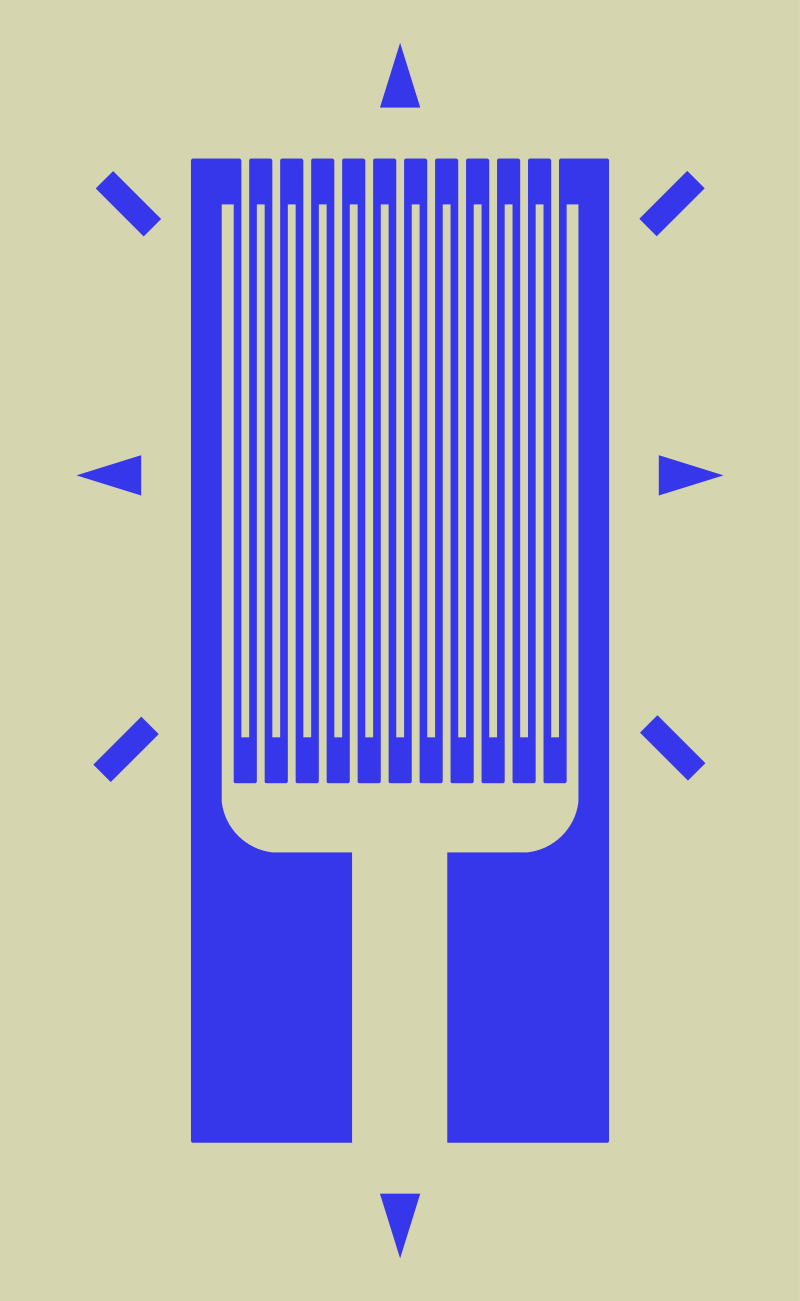
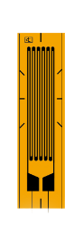
Typical foil strain gauge; the blue region is conductive and resistance is measured from one large blue pad to the other. The gauge is far more sensitive to strain in the vertical direction than in the horizontal direction. The markings outside the active area help to align the gauge during installation. |
A strain gauge is a device used to measure strain on an object. Invented by Edward E. Simmons and Arthur C. Ruge in 1938, the most common type of strain gauge consists of an insulating flexible backing which supports a metallic foil pattern.
The gauge is attached to the object by a suitable adhesive, such as cyanoacrylate. As the object is deformed, the foil is deformed, causing its electrical resistance to change.
This resistance change, usually measured using a Wheatstone bridge, is related to the strain by the quantity known as the gauge factor.
Physical operation
A strain gauge takes advantage of the physical property of electrical conductance and its dependence on the conductor's geometry. When an electrical conductor is stretched within the limits of its elasticity such that it does not break or permanently deform, it will become narrower and longer, which increases its electrical resistance end-to-end. Conversely, when a conductor is compressed such that it does not buckle, it will broaden and shorten, which decreases its electrical resistance end-to-end. From the measured electrical resistance of the strain gauge, the amount of induced stress may be inferred.
A typical strain gauge arranges a long, thin conductive strip in a zig-zag pattern of parallel lines. This does not increase the sensitivity, since the percentage change in resistance for a given strain for the entire zig-zag is the same as for any single trace. A single linear trace would have to be extremely thin, hence liable to overheating (which would change its resistance and cause it to expand), or would need to be operated at a much lower voltage, making it difficult to measure resistance changes accurately.
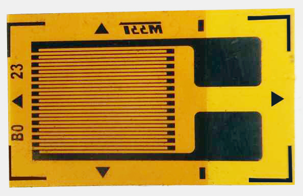 |
An unmounted resistive foil strain gauge. |
The gauge factor 
.jpg)
where
Δ R is the change in resistance caused by strain,RG is the resistance of the undeformed gauge, and ϵ is strain.
For common metallic foil gauges, the gauge factor is usually a little over 2.
For a single active gauge and three dummy resistors of the same resistance about the active gauge in a balanced Wheatstone bridge configuration, the output sensor voltage S V {\displaystyle SV} 
where 
Foil gauges typically have active areas of about 2–10 mm2 in size. With careful installation, the correct gauge, and the correct adhesive, strains up to at least 10% can be measured.
In practice
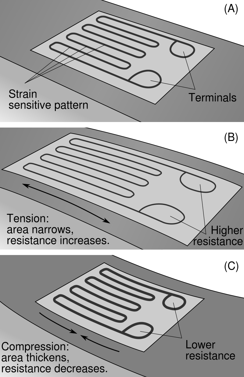 |
| Visualization of the working concept behind the strain gauge on a beam under exaggerated bending. |
An excitation voltage is applied to input leads of the gauge network, and a voltage reading is taken from the output leads. Typical input voltages are 5 V or 12 V and typical output readings are in millivolts.
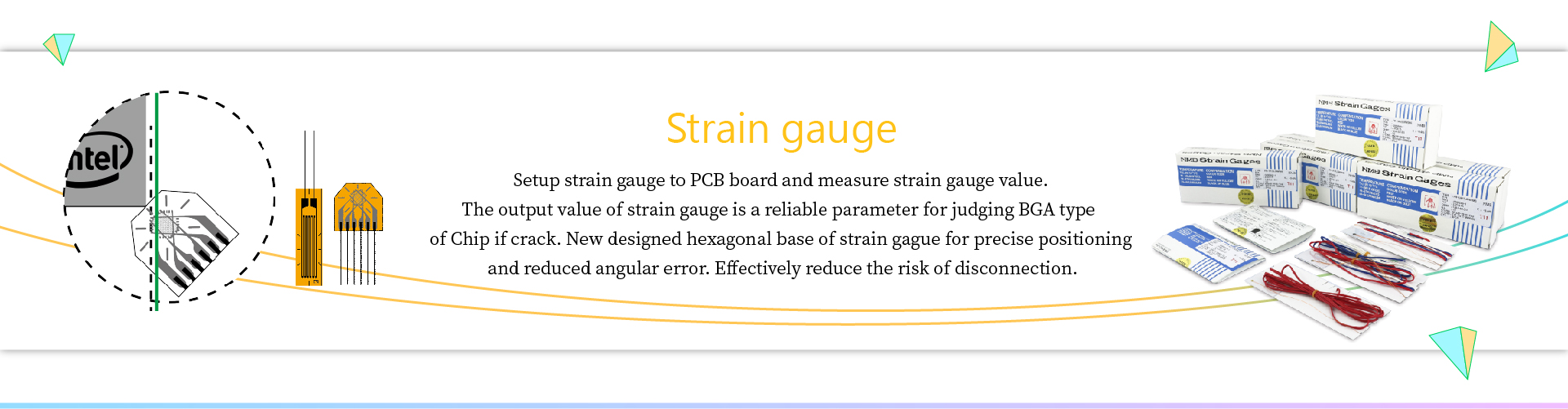
Foil strain gauges are used in many situations. Different applications place different requirements on the gauge. In most cases the orientation of the strain gauge is significant.
Gauges attached to a load cell would normally be expected to remain stable over a period of years, if not decades; while those used to measure response in a dynamic experiment may only need to remain attached to the object for a few days, be energized for less than an hour, and operate for less than a second.
Strain gauges are attached to the substrate with a special glue. The type of glue depends on the required lifetime of the measurement system. For short term measurements (up to some weeks) cyanoacrylate glue is appropriate, for long lasting installation epoxy glue is required. Usually epoxy glue requires high temperature curing (at about 80-100 °C). The preparation of the surface where the strain gauge is to be glued is of the utmost importance. The surface must be smoothed (e.g. with very fine sand paper), deoiled with solvents, the solvent traces must then be removed and the strain gauge must be glued immediately after this to avoid oxidation or pollution of the prepared area. If these steps are not followed the strain gauge binding to the surface may be unreliable and unpredictable measurement errors may be generated.
Strain gauge based technology is utilized commonly in the manufacture of pressure sensors. The gauges used in pressure sensors themselves are commonly made from silicon, polysilicon, metal film, thick film, and bonded foil.
Variations in temperature will cause a multitude of effects. The object will change in size by thermal expansion, which will be detected as a strain by the gauge. Resistance of the gauge will change, and resistance of the connecting wires will change.
Most strain gauges are made from a constantan alloy.
Various constantan alloys and Karma alloys have been designed so that the temperature effects on the resistance of the strain gauge itself largely cancel out the resistance change of the gauge due to the thermal expansion of the object under test. Because different materials have different amounts of thermal expansion, self-temperature compensation (STC) requires selecting a particular alloy matched to the material of the object under test.
Strain gauges that are not self-temperature-compensated (such as isoelastic alloy) can be temperature compensated by use of the dummy gauge technique. A dummy gauge (identical to the active strain gauge) is installed on an unstrained sample of the same material as the test specimen. The sample with the dummy gauge is placed in thermal contact with the test specimen, adjacent to the active gauge. The dummy gauge is wired into a Wheatstone bridge on an adjacent arm to the active gauge so that the temperature effects on the active and dummy gauges cancel each other. (Murphy's Law was originally coined in response to a set of gauges being incorrectly wired into a Wheatstone bridge.)
Every material reacts when it heats up or when it cools down. This will cause strain gauges to register a deformation in the material which will make it change signal. To prevent this from happening strain gauges are made so they will compensate this change due to temperature. Dependent on the material of the surface where the strain gauge is assembled on, a different expansion can be measured.
Temperature effects on the lead wires can be cancelled by using a "3-wire bridge" or a "4-wire ohm circuit" (also called a "4-wire Kelvin connection").
In any case it is a good engineering practice to keep the Wheatstone bridge voltage drive low enough to avoid the self heating of the strain gauge. The self heating of the strain gauge depends on its mechanical characteristic (large strain gauges are less prone to self heating). Low voltage drive levels of the bridge reduce the sensitivity of the overall system.
Errors and compensations
In some applications, strain gauges add mass and damping to the vibration profiles of the hardware they are intended to measure. In the turbomachinery industry, one used alternative to strain gauge technology in the measurement of vibrations on rotating hardware is the Non-Intrusive Stress Measurement System, which allows measurement of blade vibrations without any blade or disc-mounted hardware...
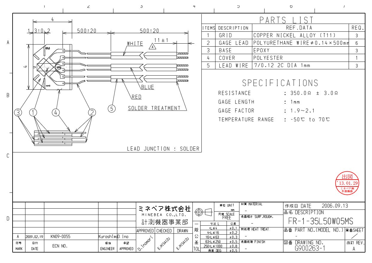 FR-1-35L50W05MS
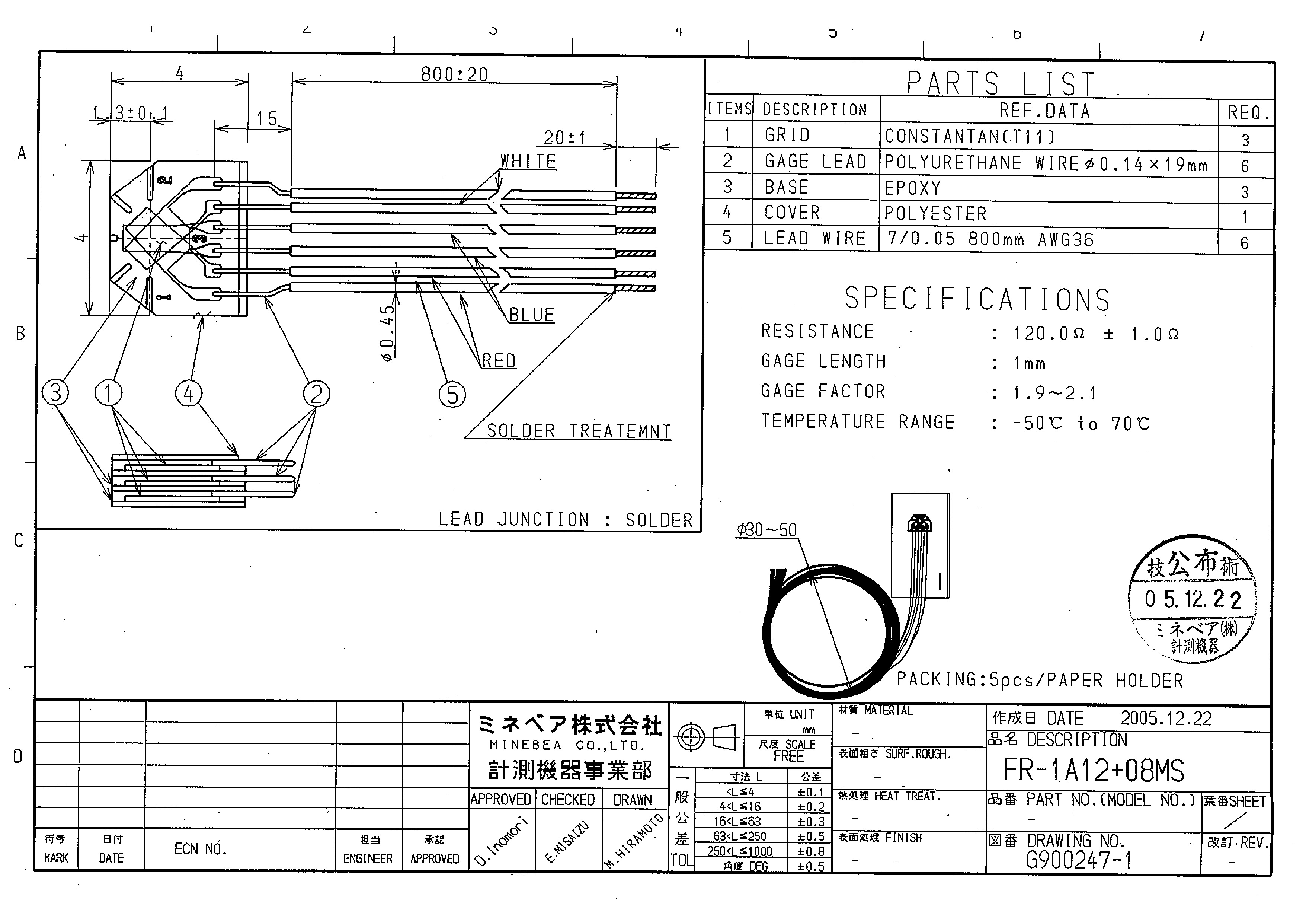 FR-1A12+08MS
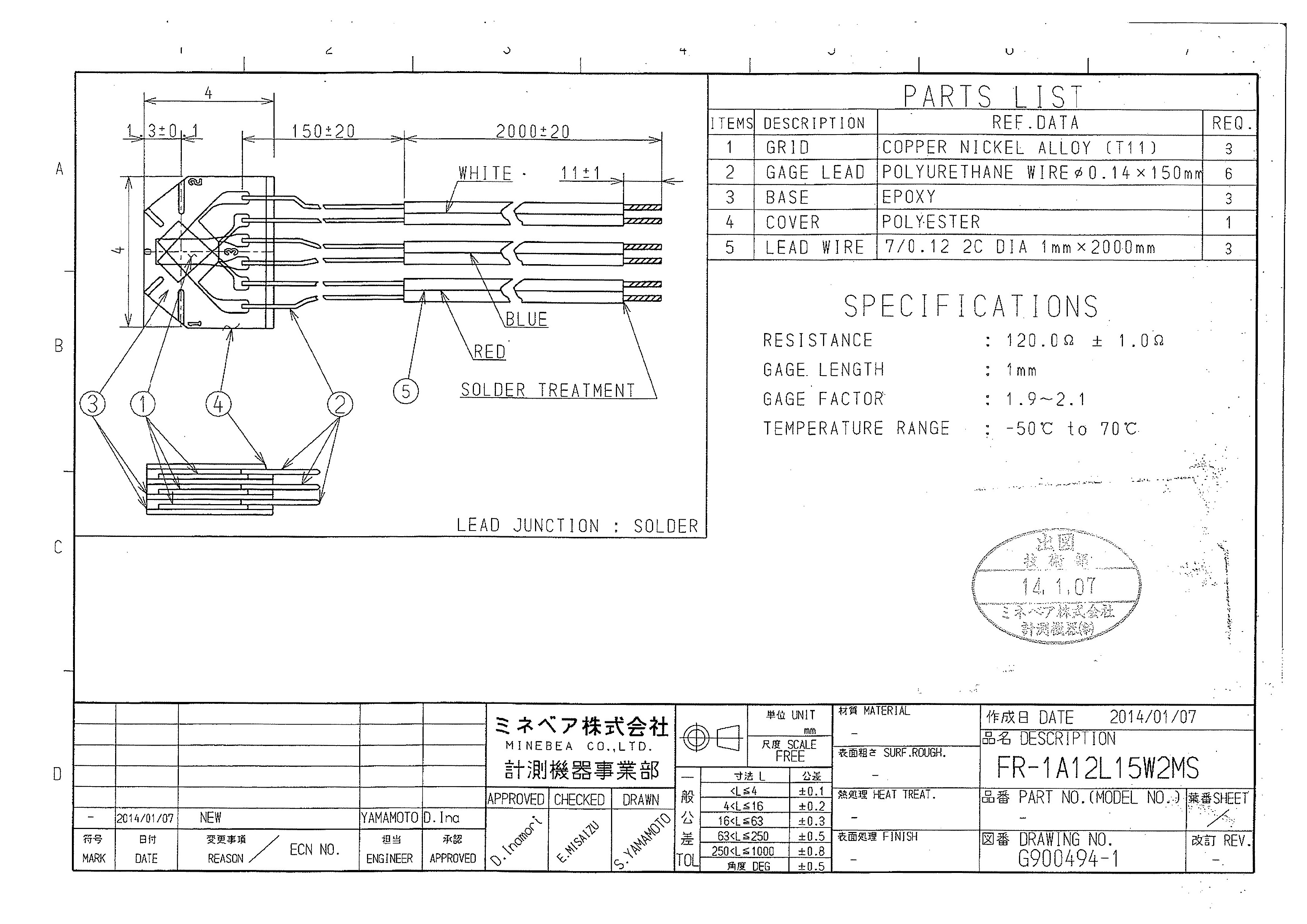 FR-1A12L15W2MS
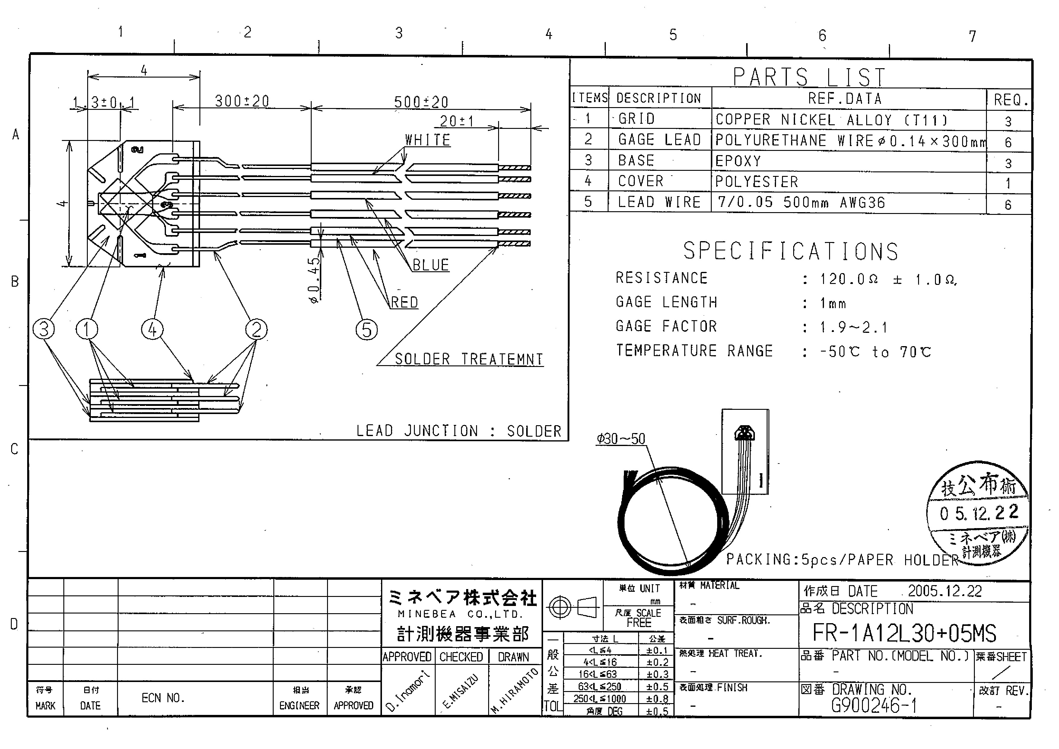 FR-1A12L30+05MS
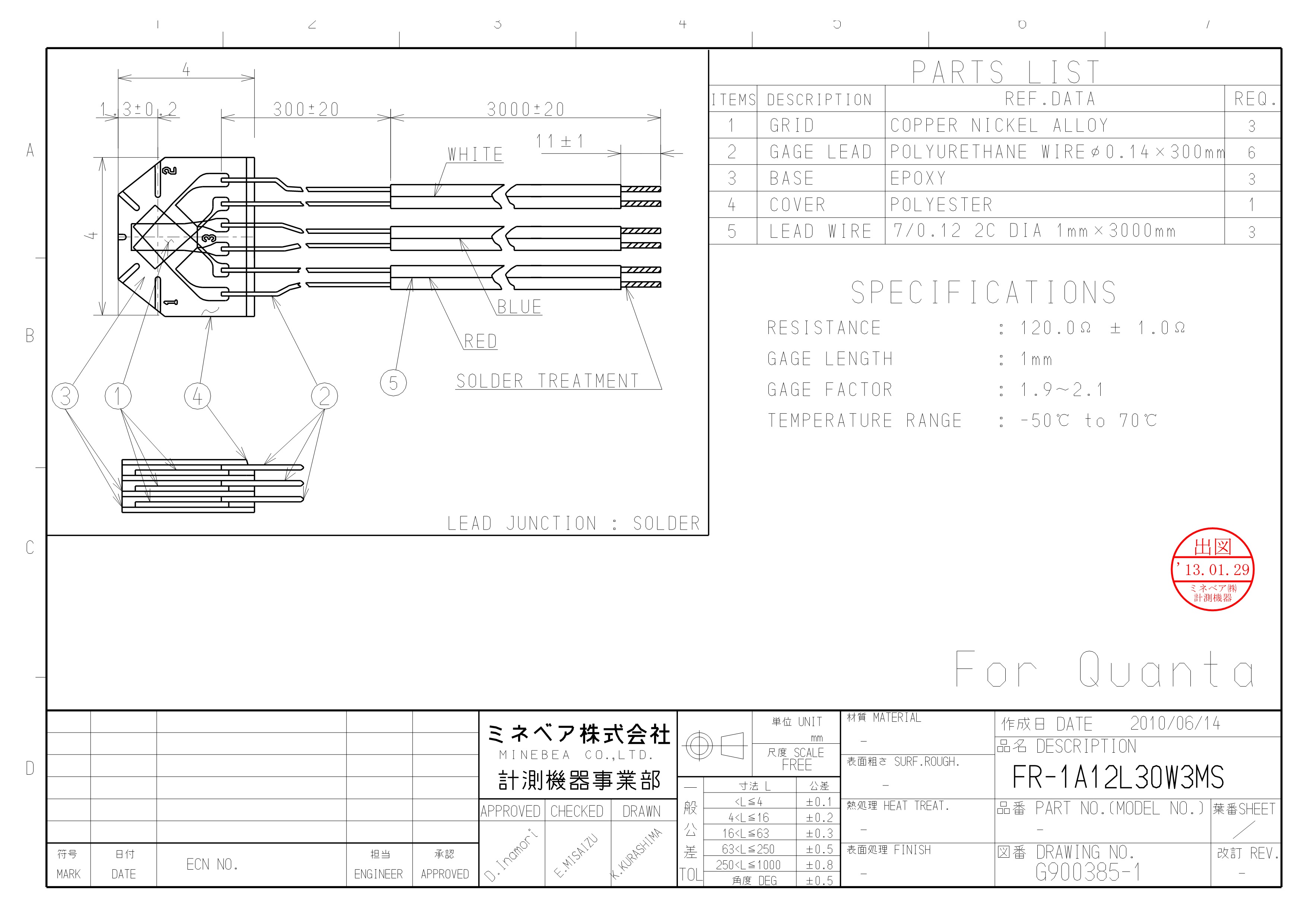 FR-1A12L30W3MS
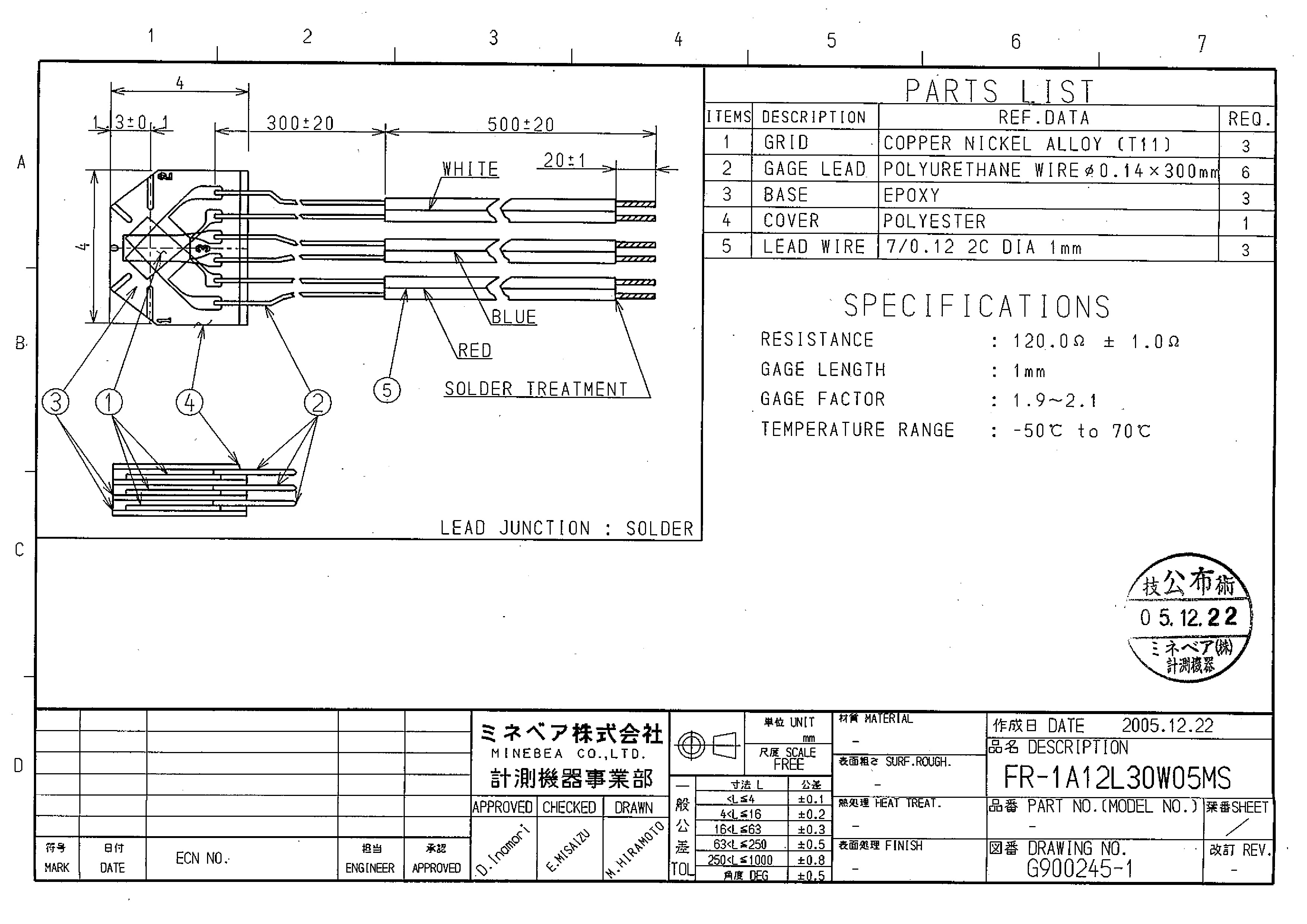 FR-1A12L30W05MS
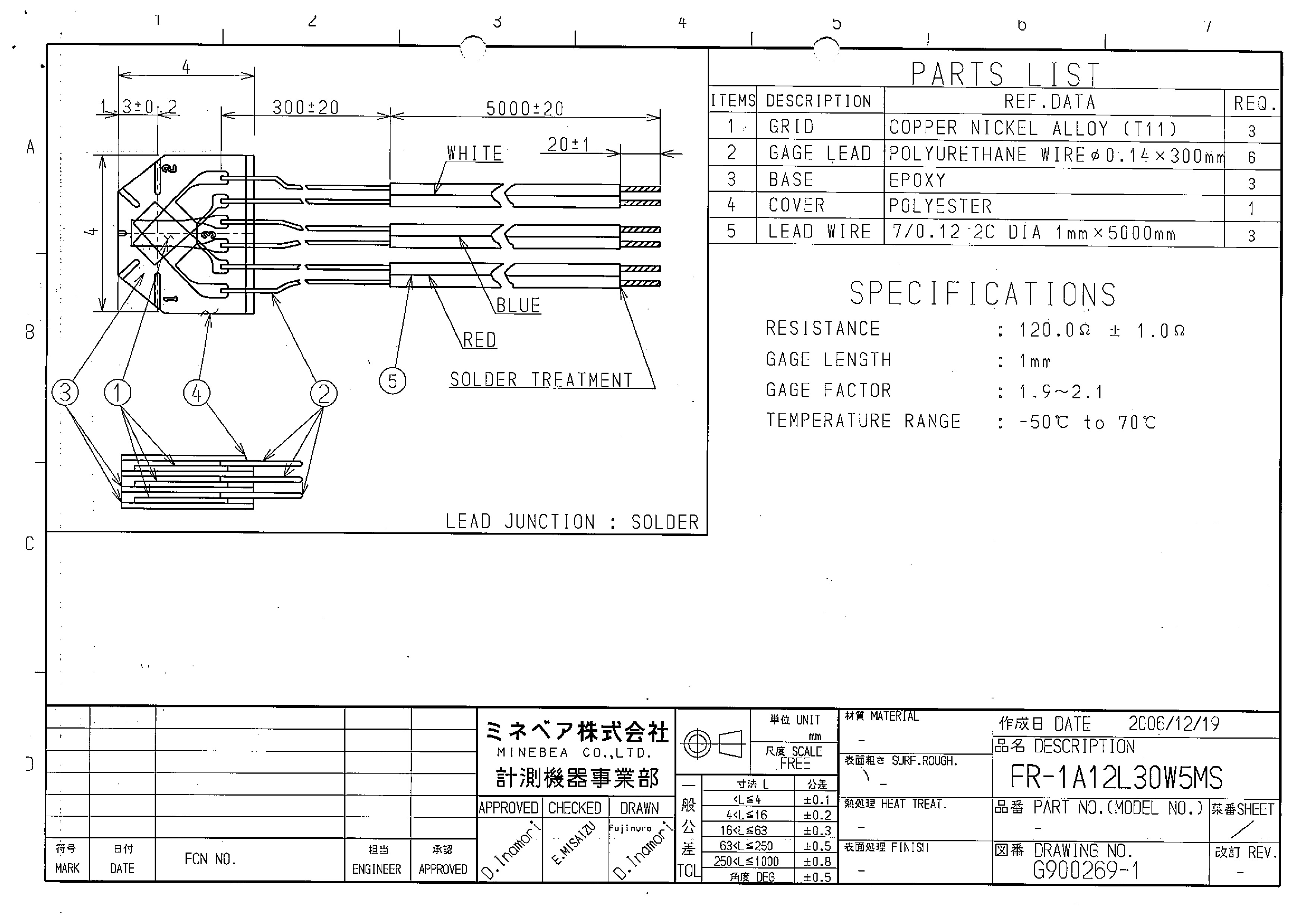 FR-1A12L30W5MS
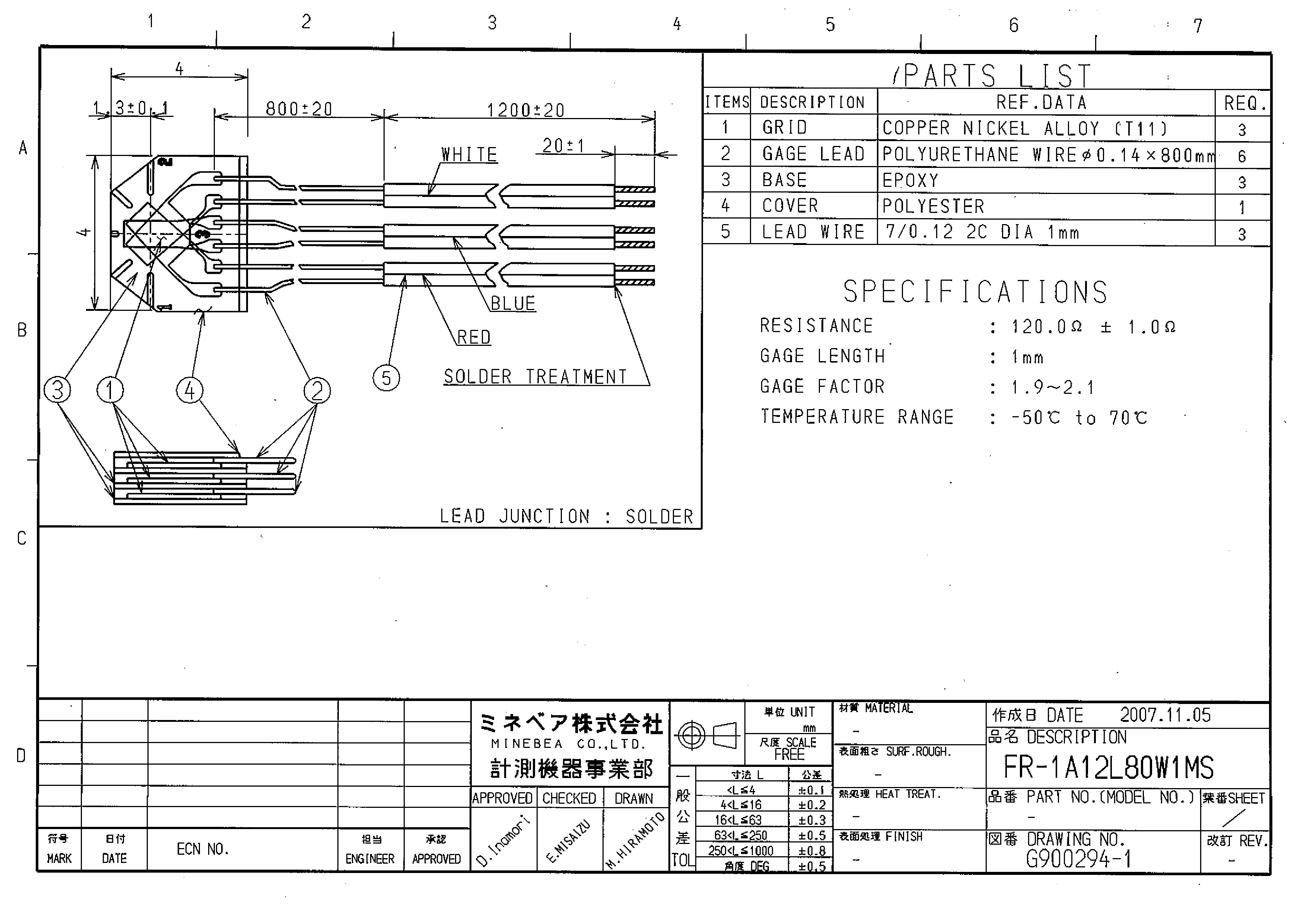 FR-1A12L80W1MS
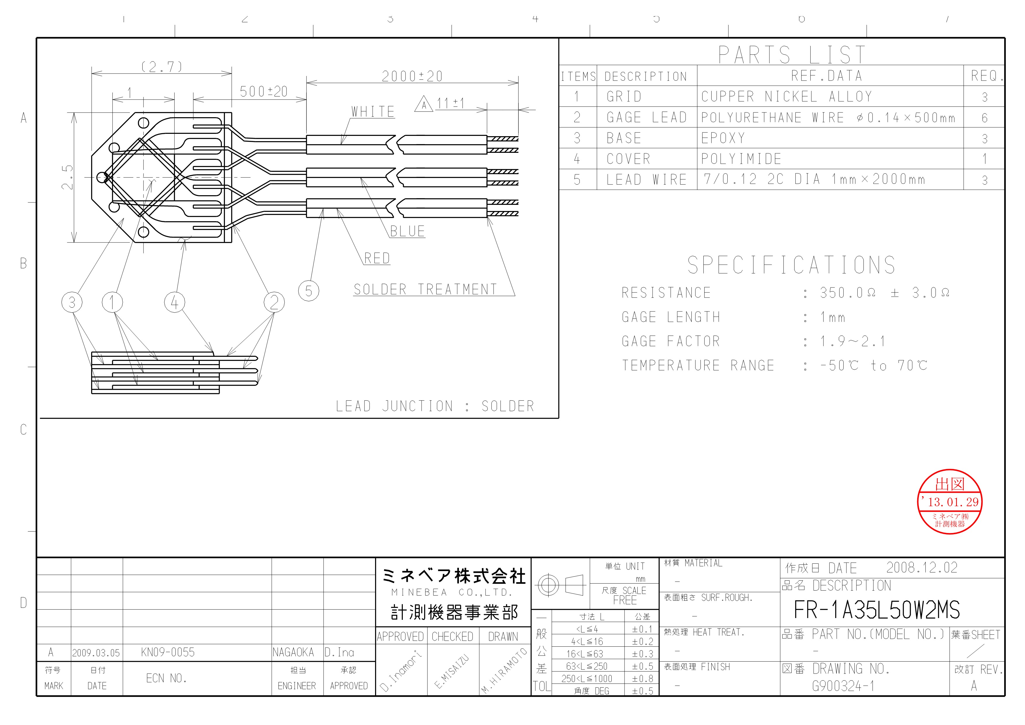 FR-1A35L50W2MS
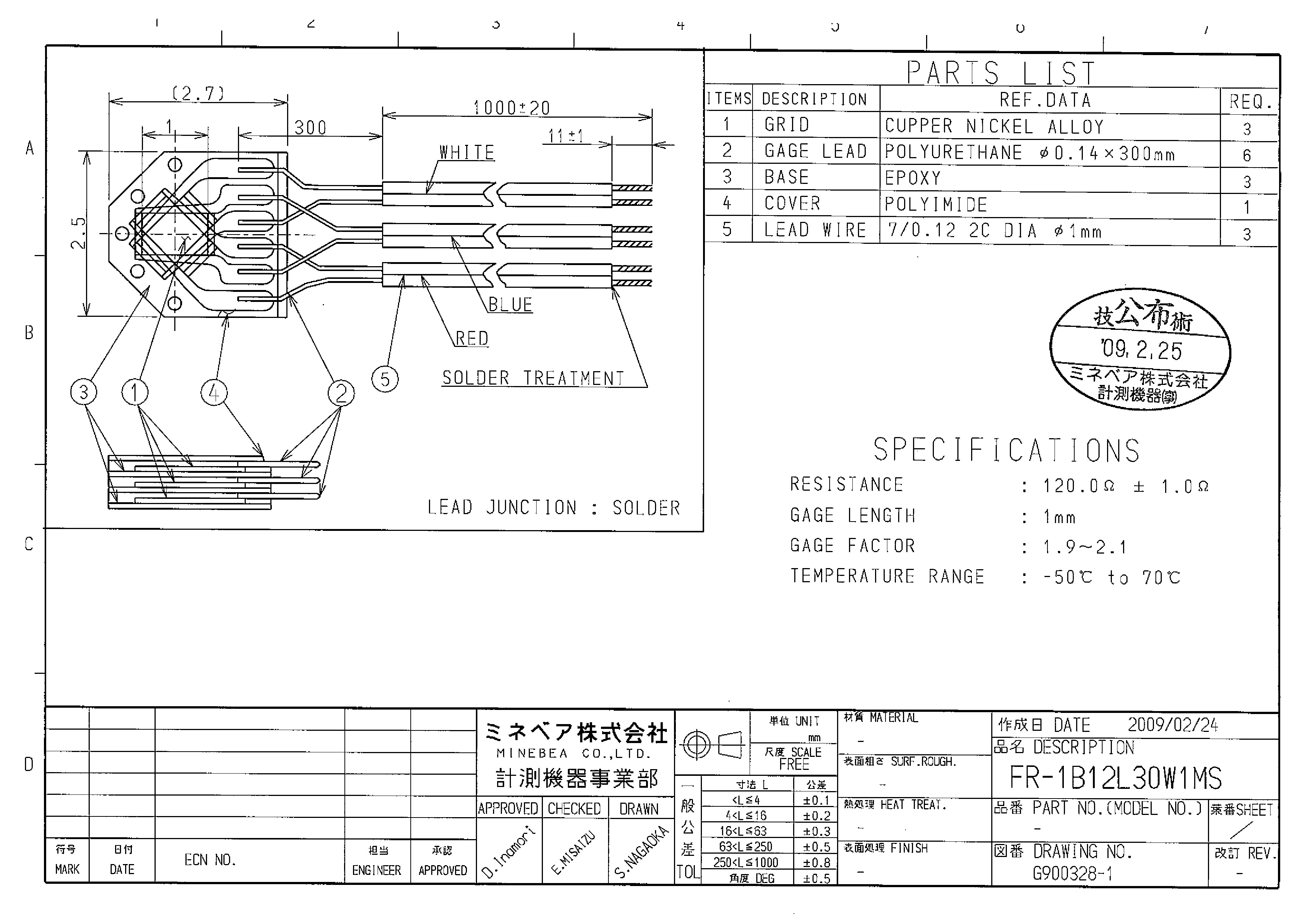 FR-1B12L30W1MS
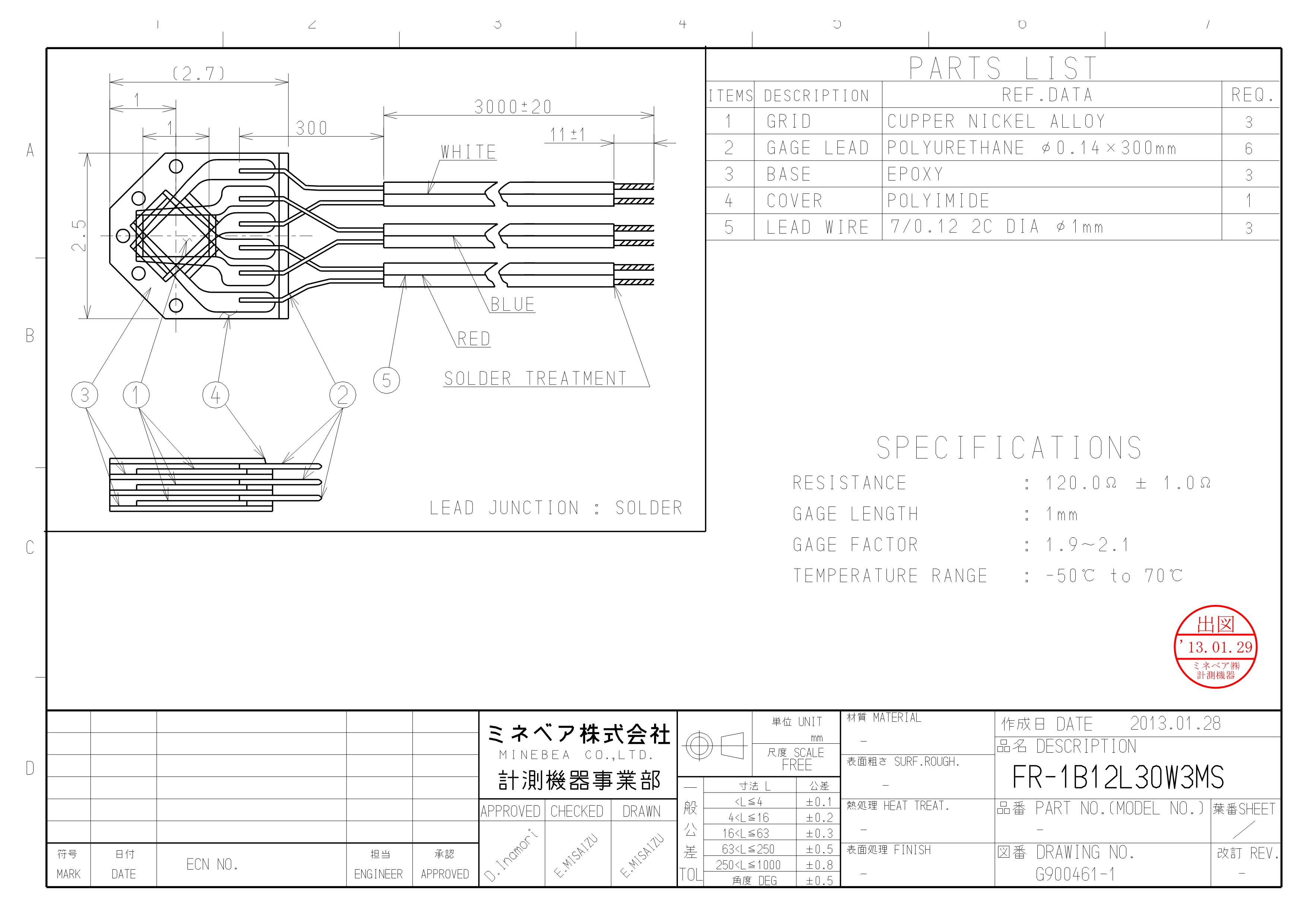 FR-1B12L30W3MS
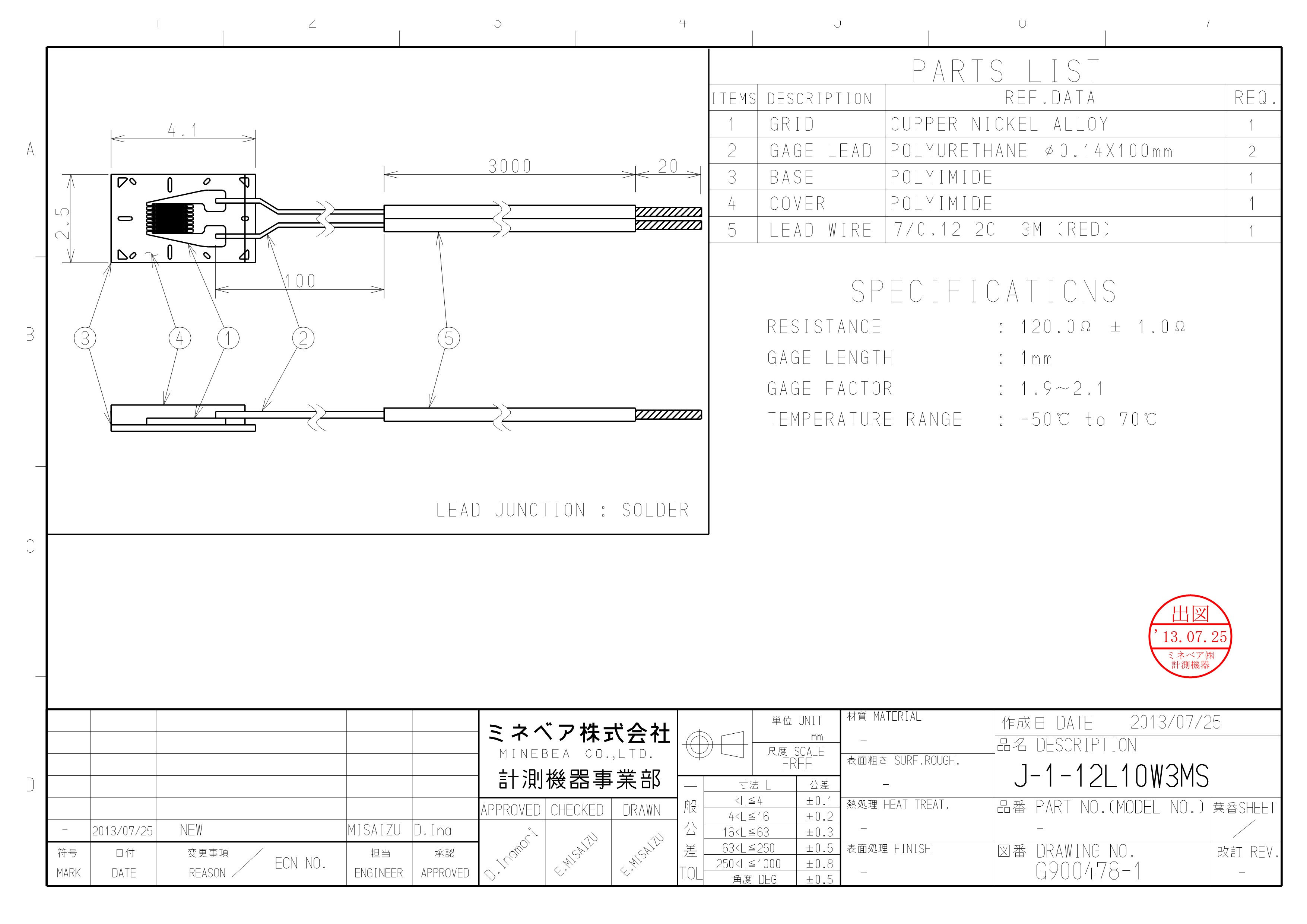 J-1-12L10W3MS_2
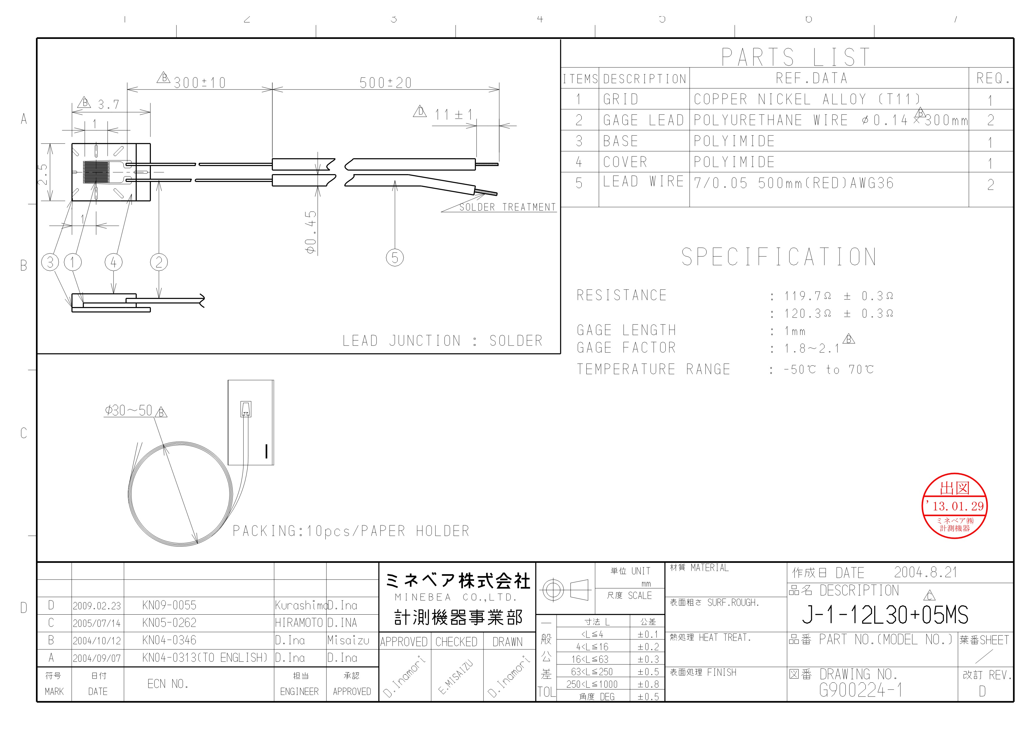 J-1-12L30+05MS
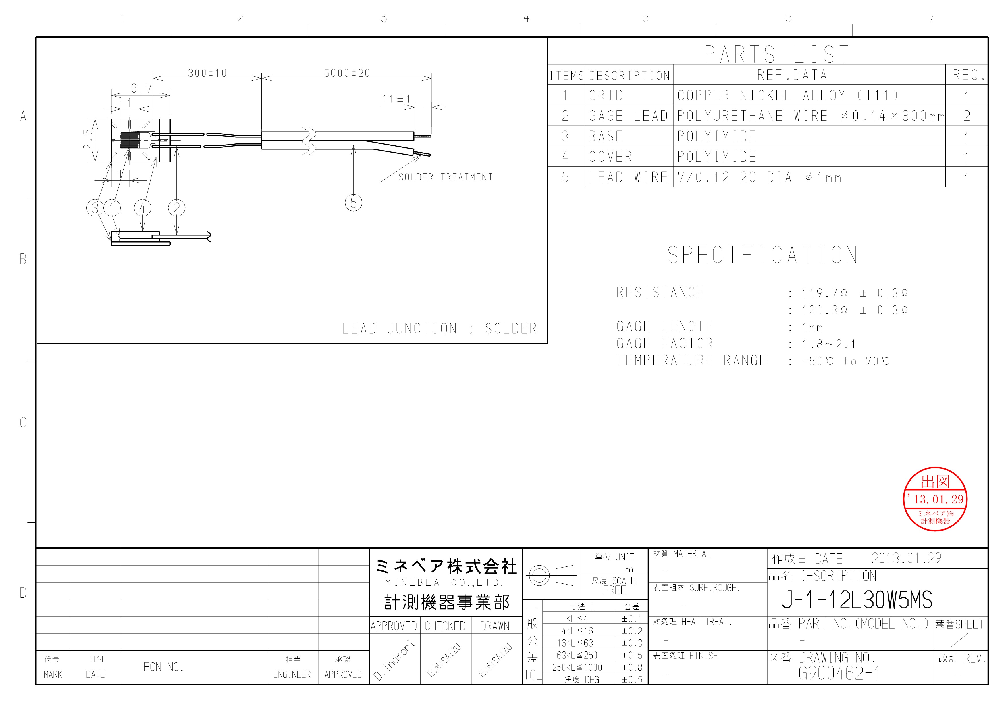 J-1-12L30W5MS
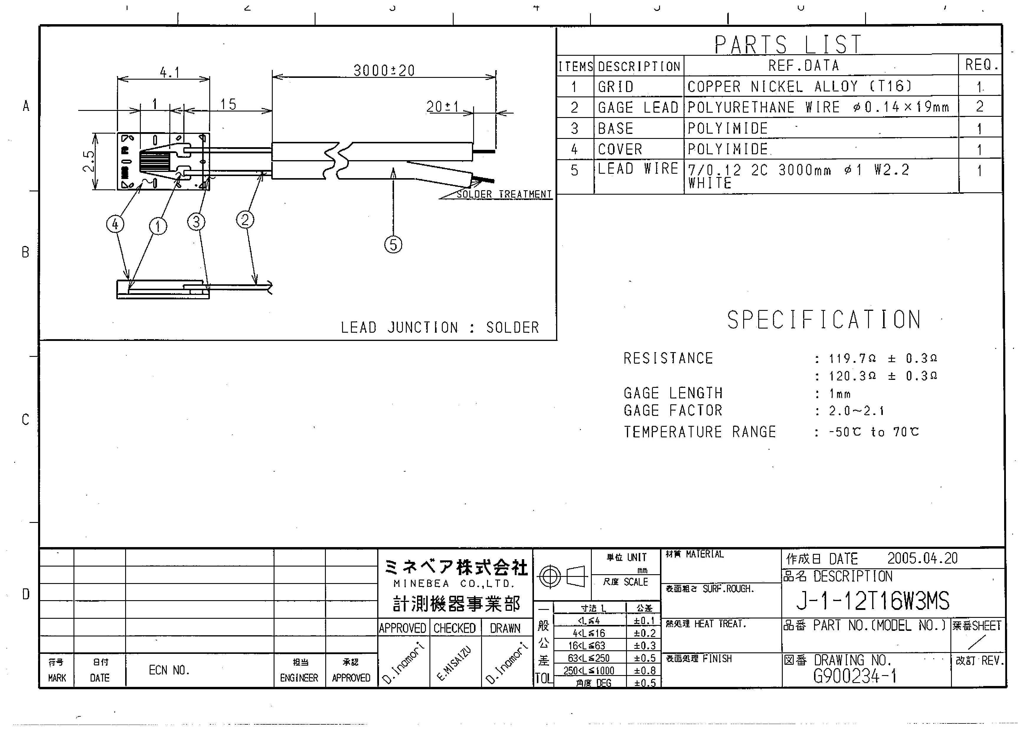 J-1-12T16W3MS
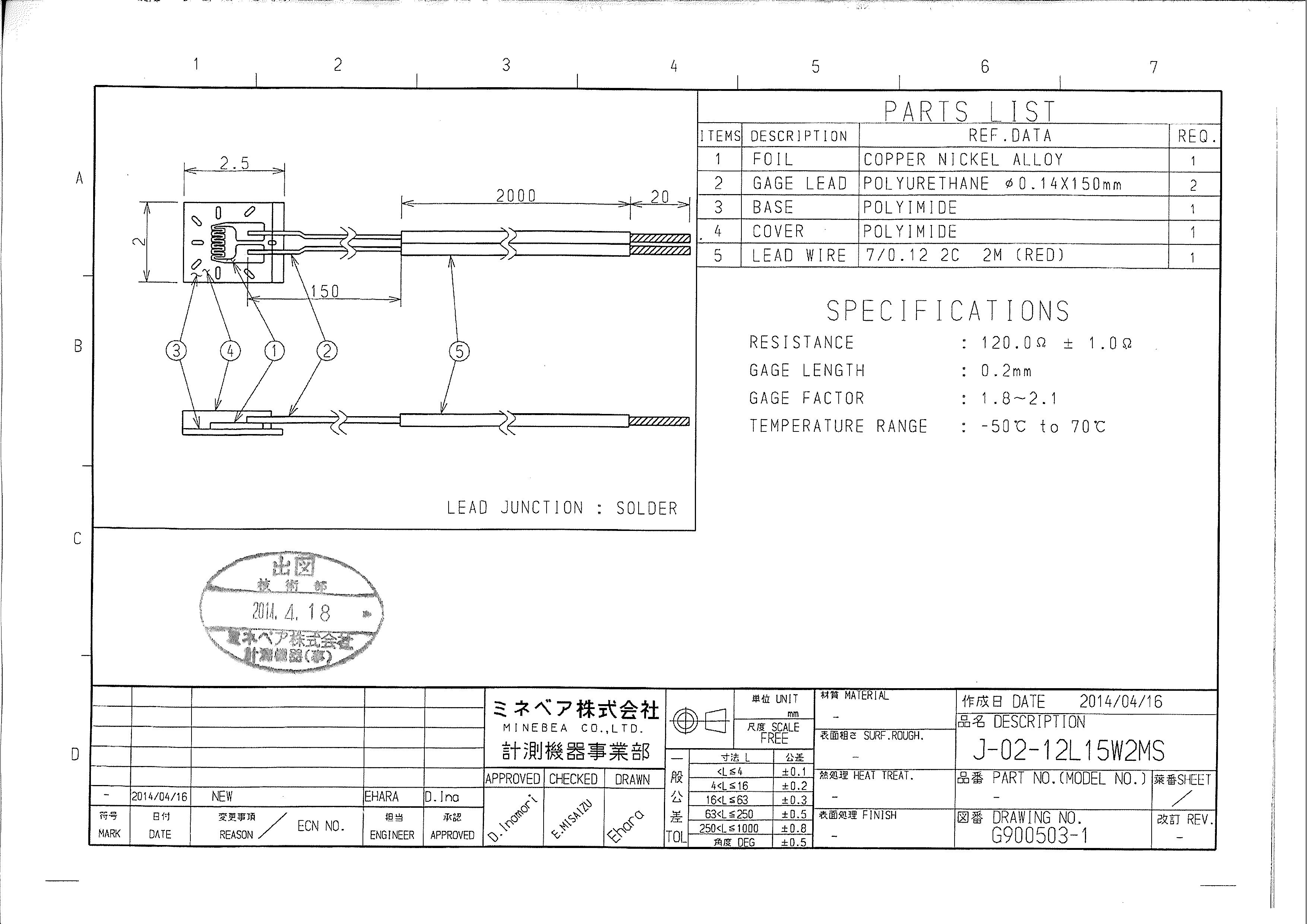 J-02-12L15W2MS
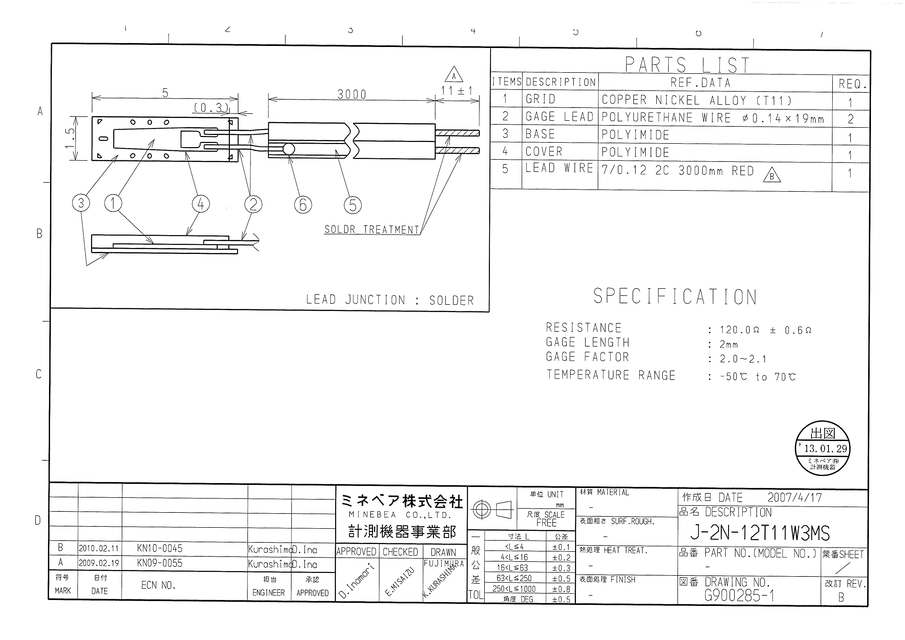 J-2N-12T11W3MS
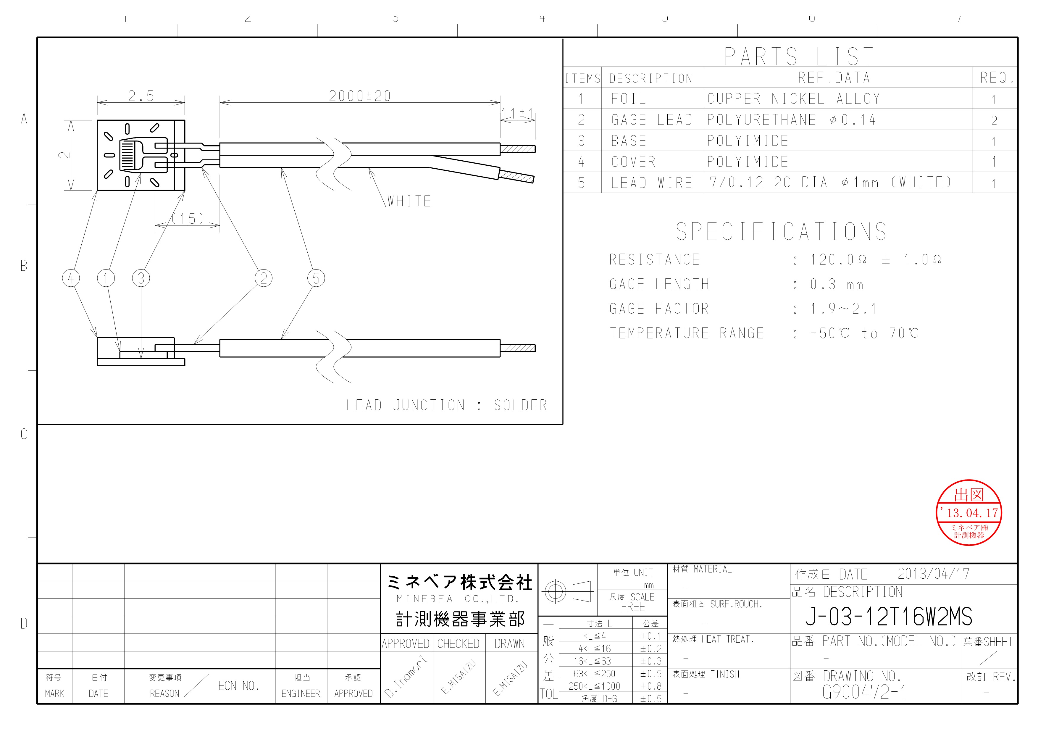 J-03-12T16W2MS
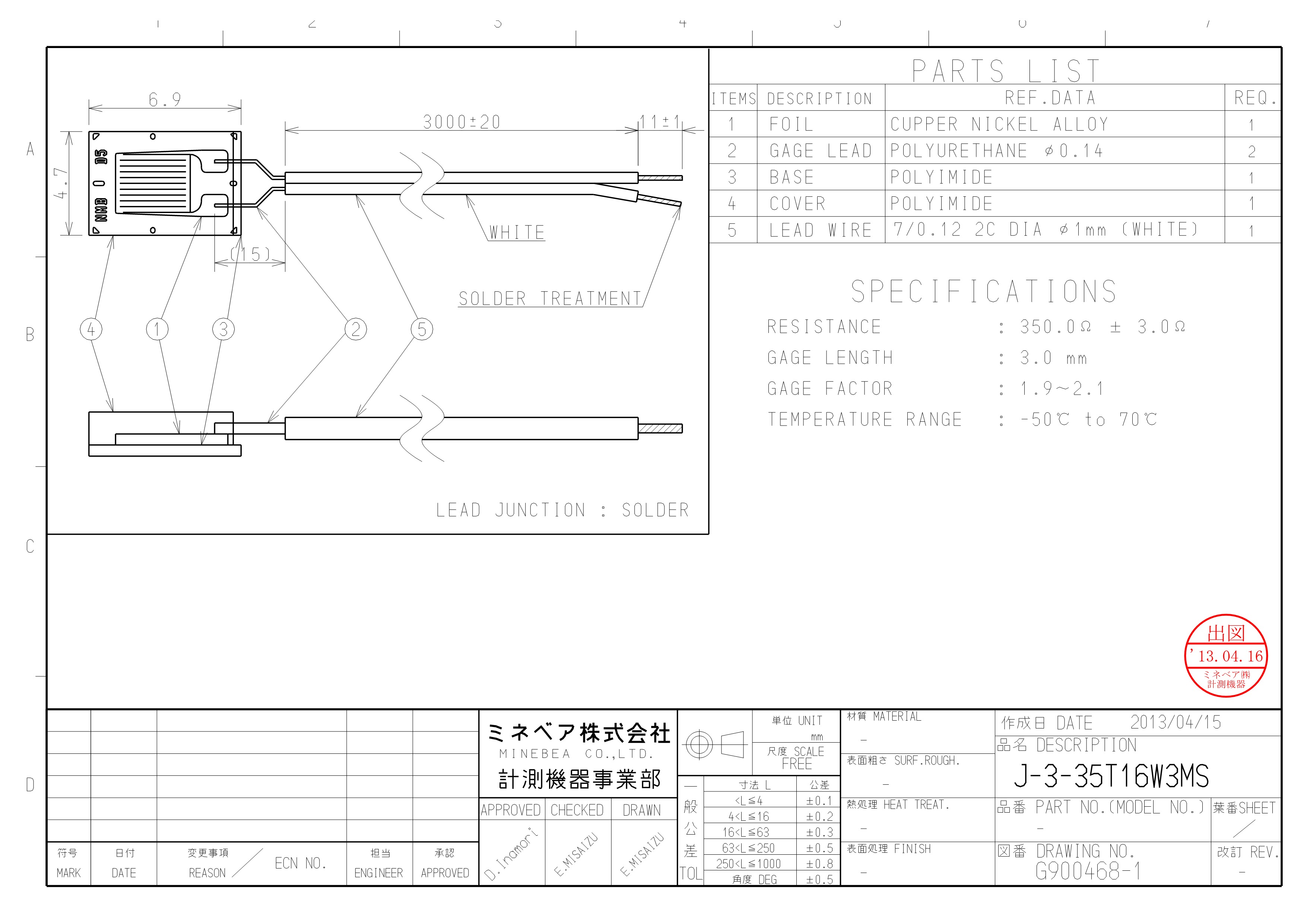 J-3-35T16W3MS
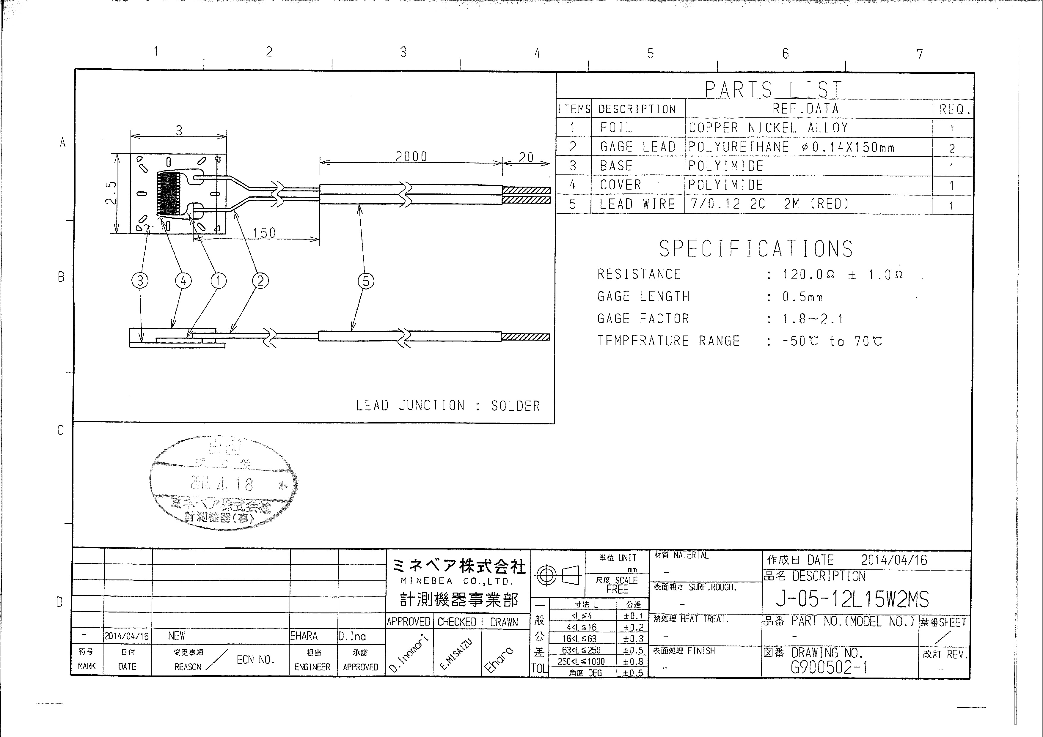 J-05-12L15W2MS
 J-5-12T11W3MS
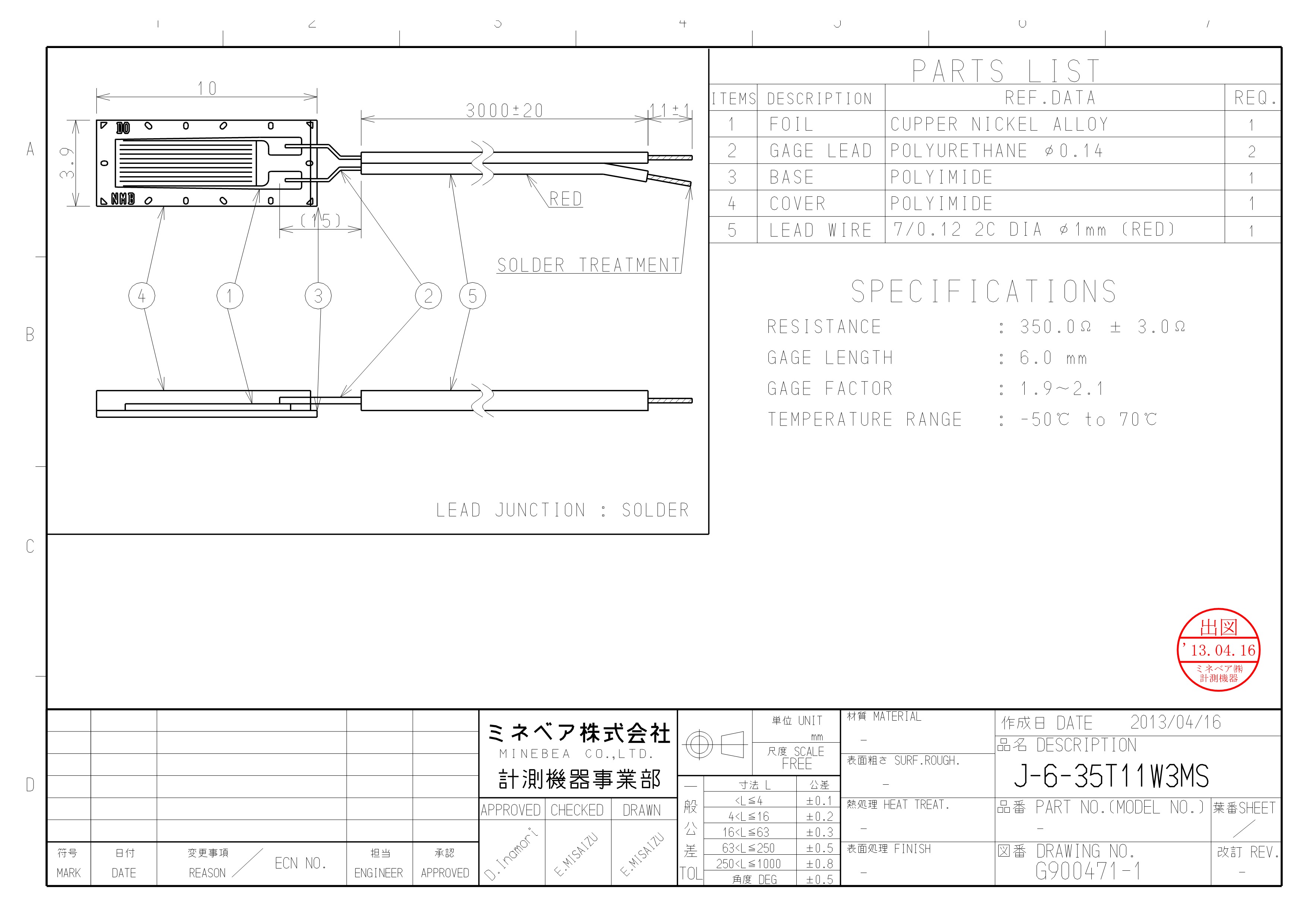 J-6-35T11W3MS
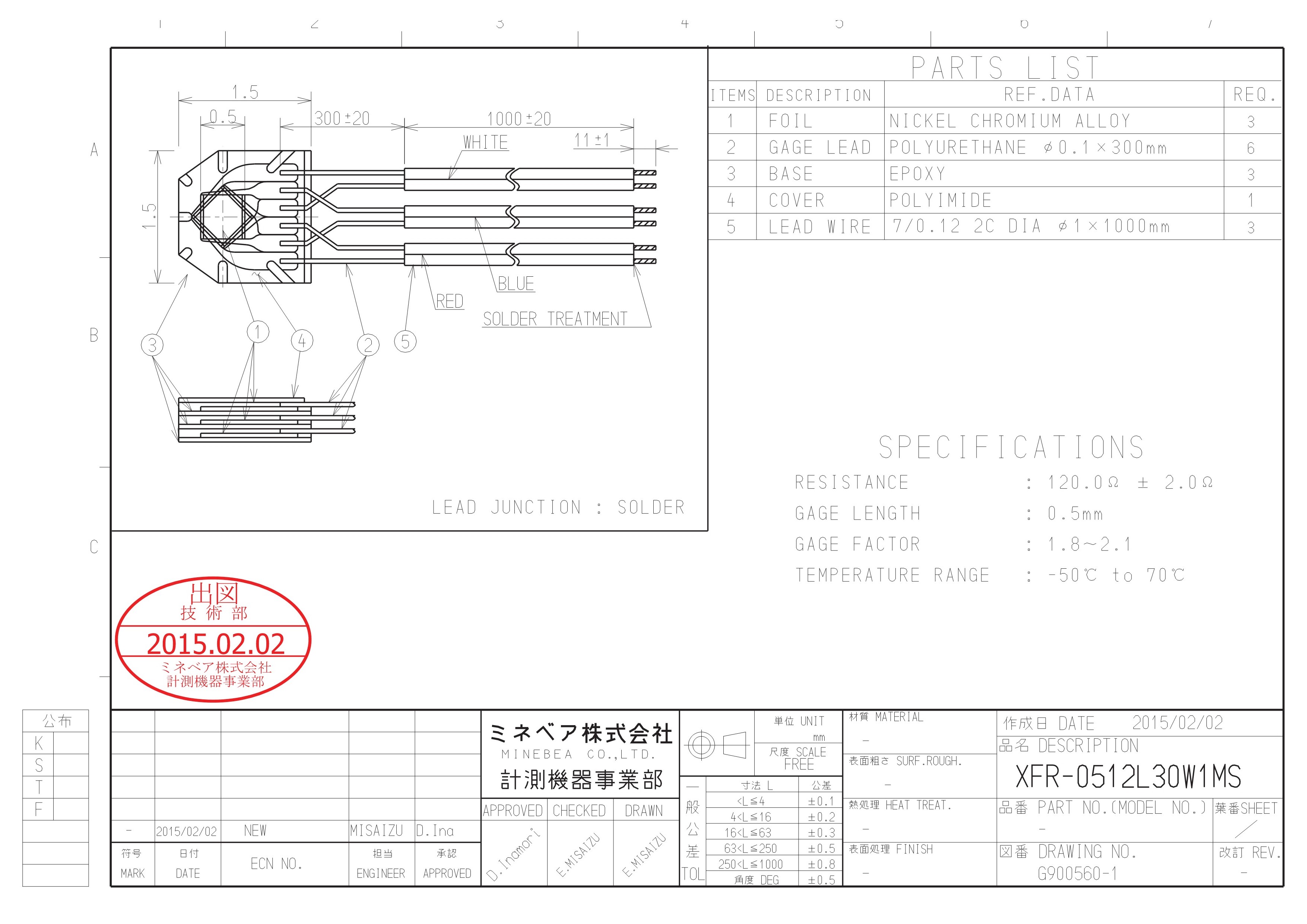 XFR-0512L30W1MS
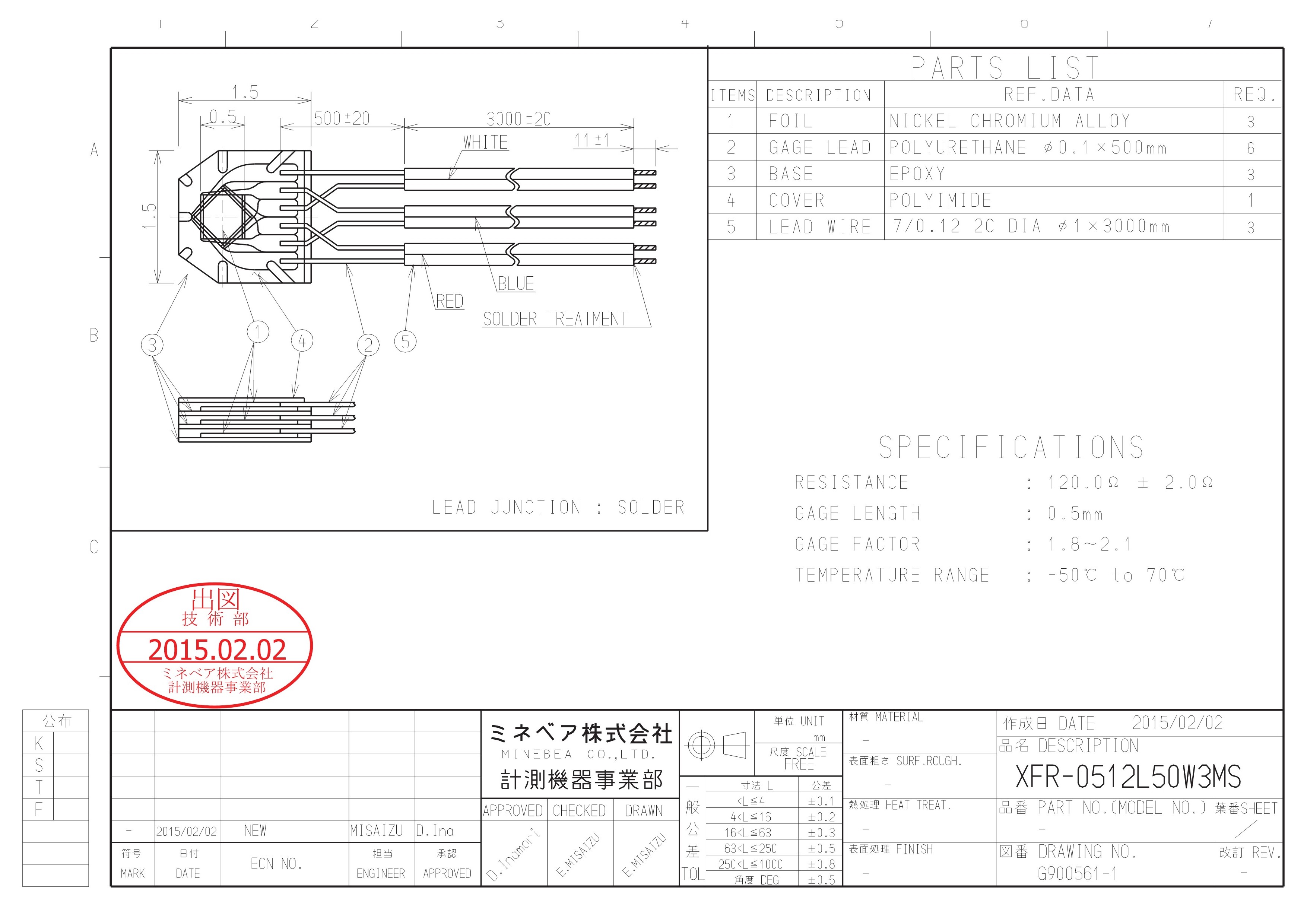 XFR-0512L50W3MS
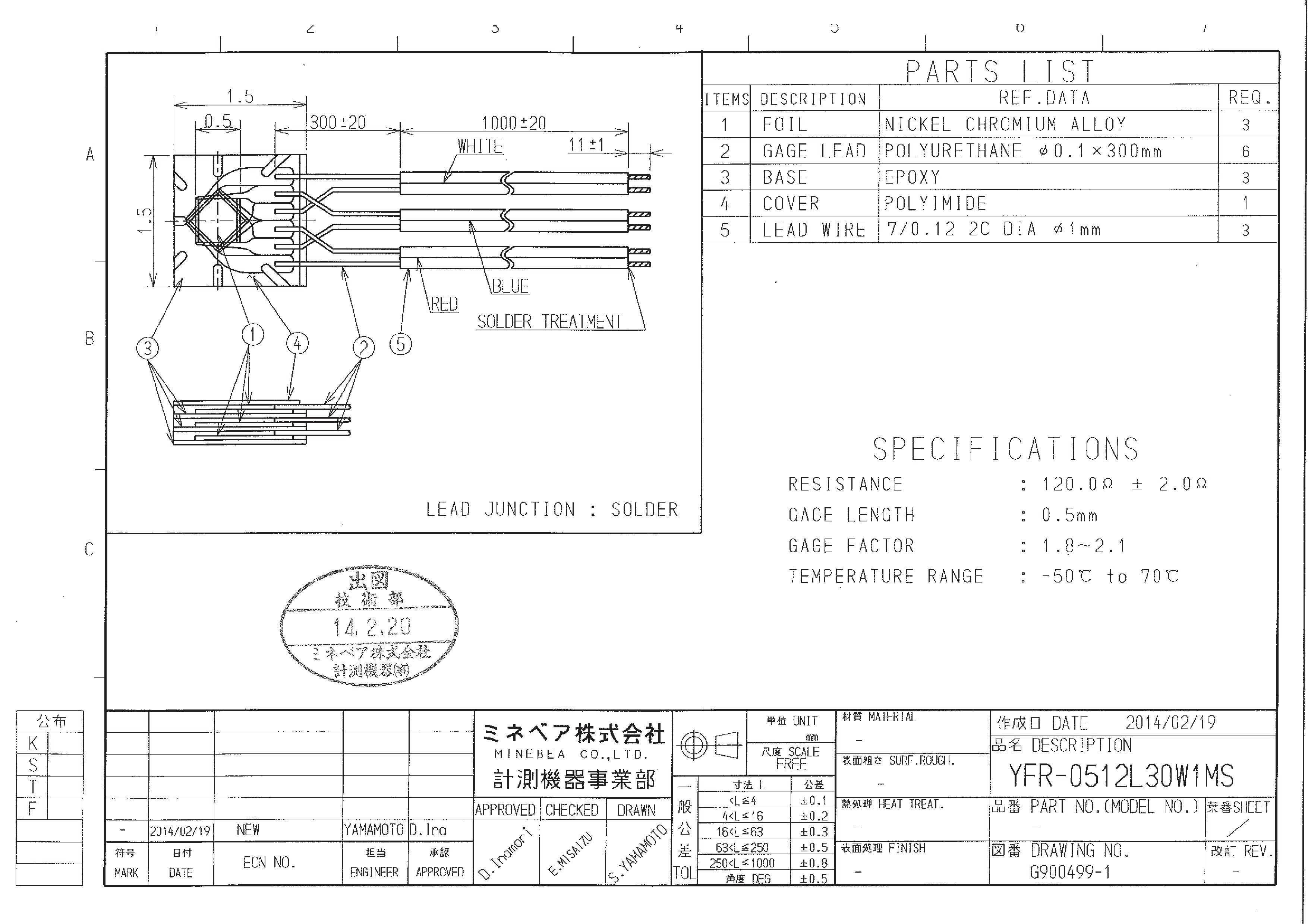 YFR-0512L30W1MS
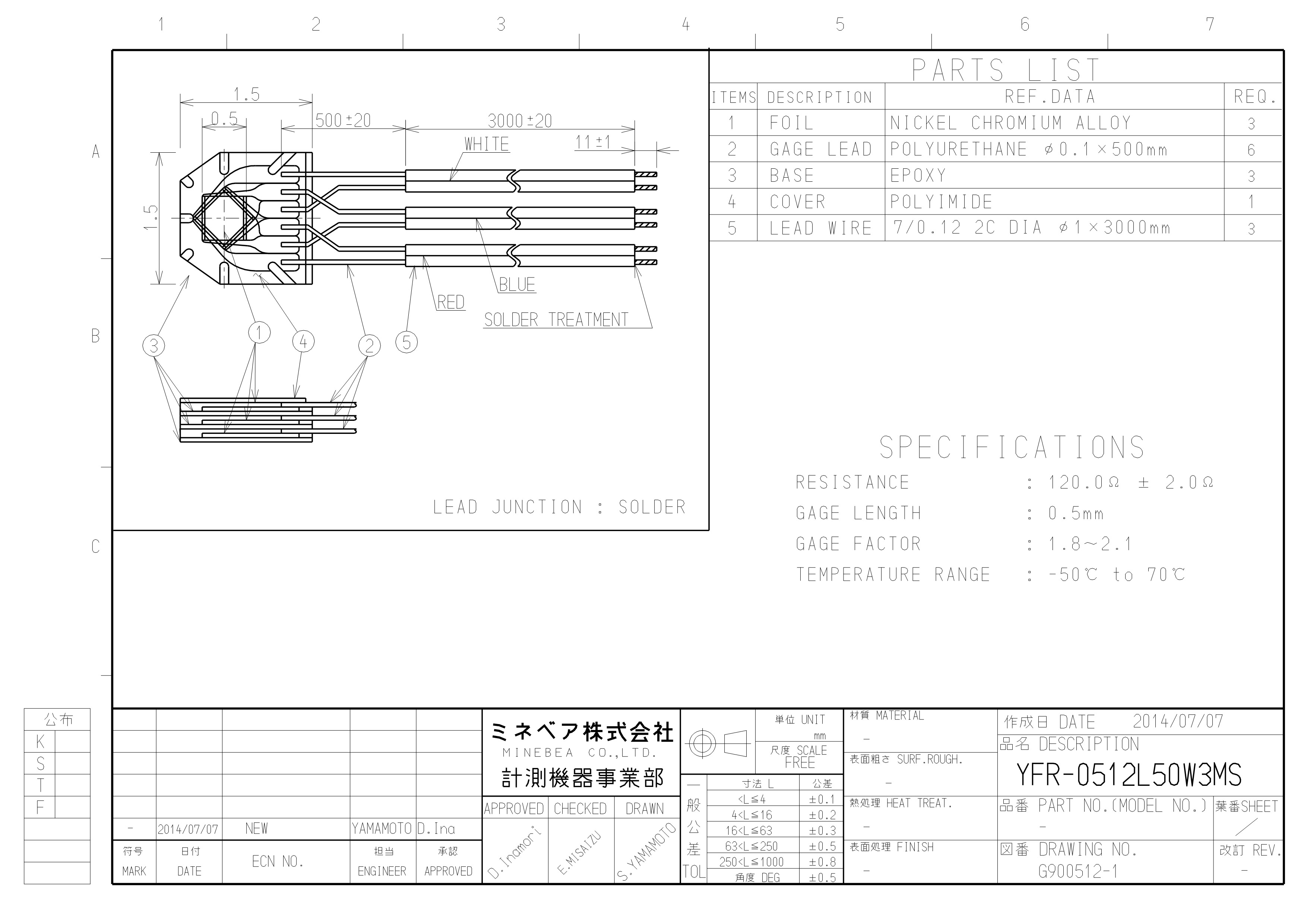 YFR-0512L50W3MS
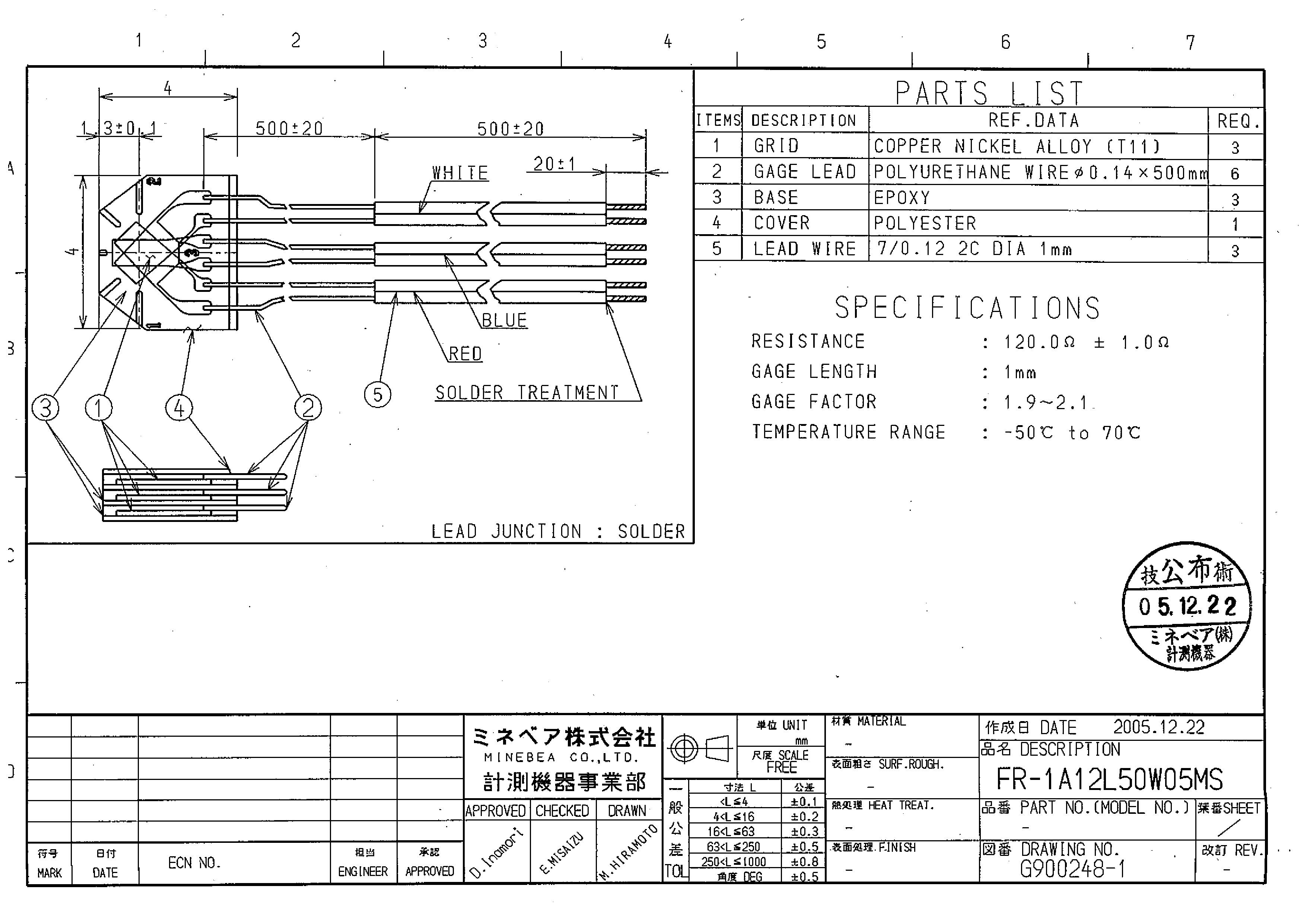 FR-1A12L50W05MS
 |
3 Axis |
|
Type |
Model |
Ohms(Ω) |
Gauge (mm) |
Cable (mm) |
||||||
|
Base |
Grid |
Enameled |
PVC |
|||||||
|
L |
W |
L |
W |
L |
Ø |
L |
Ø |
|||
|
3 Axis 0°/45°/90° |
120 |
1.5 |
1.5 |
0.5 |
0.5 |
300 |
0.14 |
1,000 |
1.0 |
|
|
3 Axis 0°/45°/90° |
120 |
1.5 |
1.5 |
0.5 |
0.5 |
300 |
0.14 |
1,000 |
1.0 |
|
|
3 Axis 0°/45°/90° |
120 |
1.5 |
1.5 |
0.5 |
0.5 |
300 |
0.14 |
1,000 |
1.0 |
|
|
3 Axis 0°/45°/90° |
120 |
1.5 |
1.5 |
0.5 |
0.5 |
500 |
0.14 |
3,000 |
1.0 |
|
|
3 Axis 0°/45°/90° |
120 |
2.7 |
2.5 |
1.0 |
0.63 |
300 |
0.14 |
1,000 |
1.0 |
|
|
3 Axis 0°/45°/90° |
120 |
2.7 |
2.5 |
1.0 |
0.63 |
300 |
0.14 |
3,000 |
1.0 |
|
|
3 Axis 0°/45°/90° |
120 |
4.0 |
4.0 |
1.0 |
0.63 |
150 |
0.14 |
200 |
1.0 |
|
|
3 Axis 0°/45°/90° |
120 |
4.0 |
4.0 |
1.0 |
0.63 |
300 |
0.14 |
500 |
1.0 |
|
|
3 Axis 0°/45°/90° |
120 |
4.0 |
4.0 |
1.0 |
0.63 |
300 |
0.14 |
500 |
0.45 |
|
|
3 Axis 0°/45°/90° |
120 |
4.0 |
4.0 |
1.0 |
0.63 |
300 |
0.14 |
300 |
1.0 |
|
|
3 Axis 0°/45°/90° |
120 |
4.0 |
4.0 |
1.0 |
0.63 |
300 |
0.14 |
5,000 |
1.0 |
|
|
3 Axis 0°/45°/90° |
120 |
4.0 |
4.0 |
1.0 |
0.63 |
500 |
0.14 |
500 |
1.0 |
|
|
3 Axis 0°/45°/90° |
120 |
4.0 |
4.0 |
1.0 |
0.63 |
800 |
0.14 |
1,200 |
1.0 |
|
|
3 Axis 0°/45°/90° |
120 |
4.0 |
4.0 |
1.0 |
0.63 |
15 |
0.14 |
800 |
0.45 |
|
|
3 Axis 0°/45°/90° |
350 |
4.0 |
4.0 |
1.0 |
0.63 |
500 |
0.14 |
500 |
1.0 |
|
|
3 Axis 0°/45°/90° |
350 |
4.0 |
4.0 |
1.0 |
0.63 |
500 |
0.14 |
2,000 |
1.0 |
|
 |
1 Axis |
|
Type |
Model |
Ohms (Ω) |
Gauge (mm) |
Cable (mm) |
||||||
|
Base |
Grid |
Enameled |
PVC |
|||||||
|
L |
W |
L |
W |
L |
Ø |
L |
Ø |
|||
|
1 Axis |
120 |
2.5 |
2.0 |
0.2 |
0.63 |
150 |
0.14 |
2,000 |
1.0 |
|
|
1 Axis |
120 |
2.5 |
2.0 |
0.3 |
0.63 |
15 |
0.14 |
2,000 |
1.0 |
|
|
1 Axis |
120 |
2.5 |
2.0 |
0.5 |
0.63 |
150 |
0.14 |
2,000 |
1.0 |
|
|
1 Axis |
120 |
2.5 |
3.2 |
1.0 |
0.63 |
15 |
0.14 |
3,000 |
1.0 |
|
|
1 Axis |
120 |
2.5 |
3.2 |
1.0 |
0.63 |
100 |
0.14 |
3,000 |
1.0 |
|
|
1 Axis |
120 |
2.5 |
3.2 |
1.0 |
0.63 |
300 |
0.14 |
500 |
0.45 |
|
|
1 Axis |
120 |
2.5 |
3.2 |
1.0 |
0.63 |
300 |
0.14 |
5,000 |
1.0 |
|
|
1 Axis |
120 |
5 |
1.5 |
1.0 |
0.63 |
5 |
0.14 |
5,000 |
1.0 |
|
|
1 Axis |
120 |
6.9 |
4.7 |
3.0 |
2.0 |
15 |
0.14 |
3,000 |
1.0 |
|
|
1 Axis |
120 |
10.0 |
3.0 |
5.0 |
1.5 |
15 |
0.14 |
3,000 |
1.0 |
|
|
1 Axis |
350 |
10.0 |
3.9 |
6.0 |
2.0 |
15 |
0.14 |
3,000 |
1.0 |
|
 Language
 Search
 Inquiry Cart